If you are new in Blynk2.0, then you are in the right post. in this post you will learn, how to start with All new Blynk2.0 with Web and Mobile Dashboard. Also, you will get to learn about:
- How to create a template
- Data Stream
- Web dashboard
- How to add a new device in all new Blynk2.0
- How to add credentials Over the Air-OTA
- How to control led using Blynk2.0 mobile app
Bottom of this post, you will get all the links including programming code, circuit diagram, hardware, library, etc. related to this post.
This is the step-by-step Video demonstration of this post.
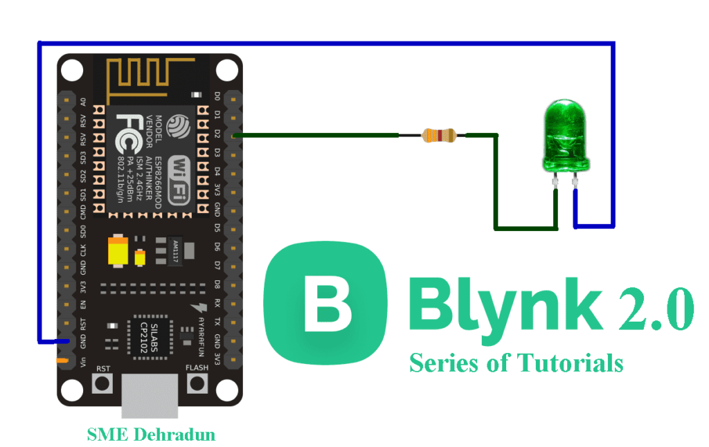
This is the circuit diagram to connect your LED to NodeMCU/ Nuttyfi.
Watch our video tutorial for this post with complete explanation.
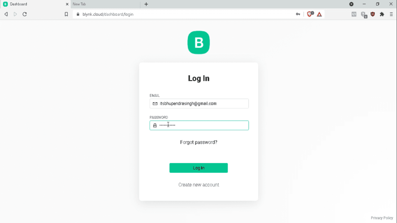
So first of all, we go to the browser and open the blynk cloud. Here you can create your new account. Just logged into your account.
A new dashboard will be opened.
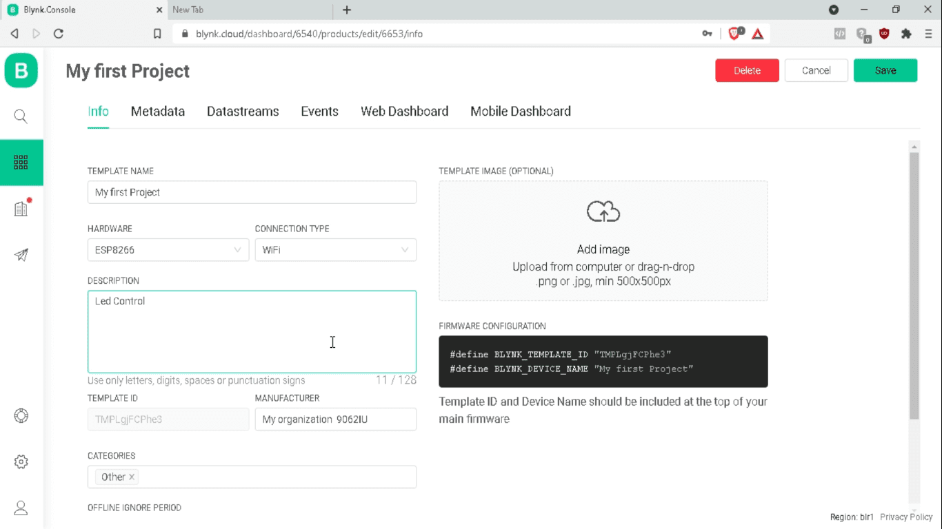
Here we click on a new template, write the name of our project. And here you can select your hardware like esp8266. ESP8266 means NodeMCU Series. Here you can write your project description and it’s done.

So, our project dashboard has been opened. This is an important part of the blynk project. The Template ID and Device name. We have to write it to our Arduino program.
This is the metadata tab, where you get all the information about your project like device name, device owner, location, etc.
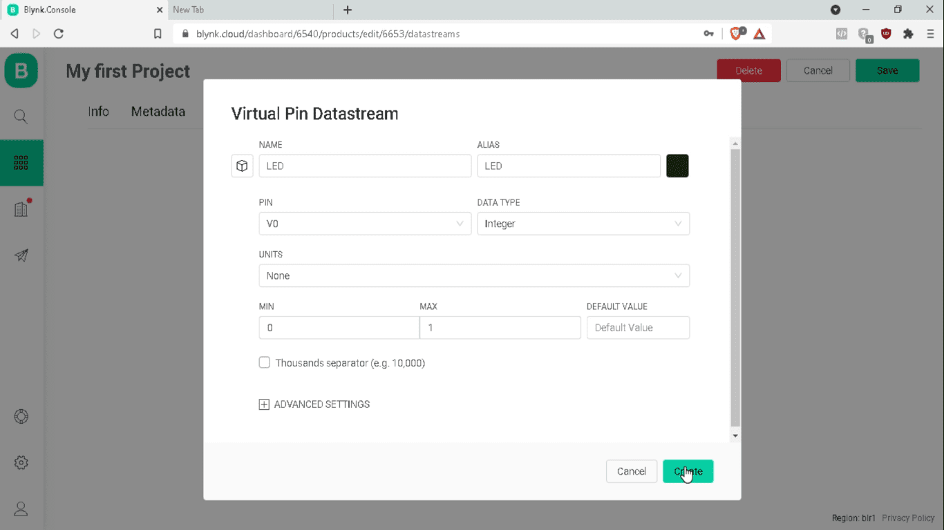
Now, we go to the DataStream tab. Here you define your method, how you are going to use the hardware, like through digital or analog pins directly or through virtual pins.
So click on the new datastream, and select the virtual pin. Now write the name of your virtual pin-like led. We take the V0 pin as our virtual pin and the integer as data type. After it, click to create. So here our virtual pin has been created.
And in the event tab, it’s displayed online and offline.
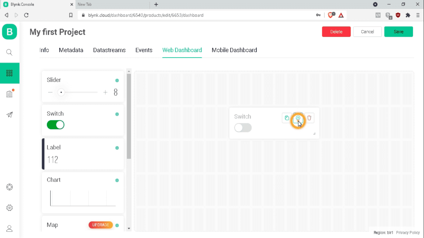
Now In the web dashboard, we drag and drop the switch widget to our dashboard. And click on the setting.
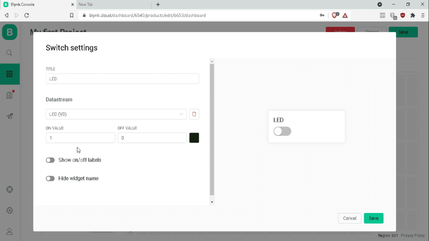
Here choose the datastream source as LED (V0). Click on the Save button.
At last in the mobile dashboard, you can download the app for your smartphone. Finally, click on the Save button.
Now, download the new library of blynk. Once you download it, you will get the zip file with the name”blynk library master“. Right-click on the blynk library master and extract it. You will get the extracted folder. Inside that folder, you will get the examples, libraries, and other supportive files. So copy this folder and go to the location where you installed the Arduino, inside this folder, you will get the library folder, go inside and paste it here. you can see the video for it at the starting of this post for a complete description of it with demonstration.
Again, go to the video description and download the programming code for your Blynk 2.0 with all supportive files. Once downloaded, you will get the folder with the name blynk 2.0 led control. Extract it. Go inside the folder and you will get the program file with the .ino extension. Open it.
On top of this program, we need to change these credentials. So go to your blynk dashboard, in the info tab you will get the credentials.
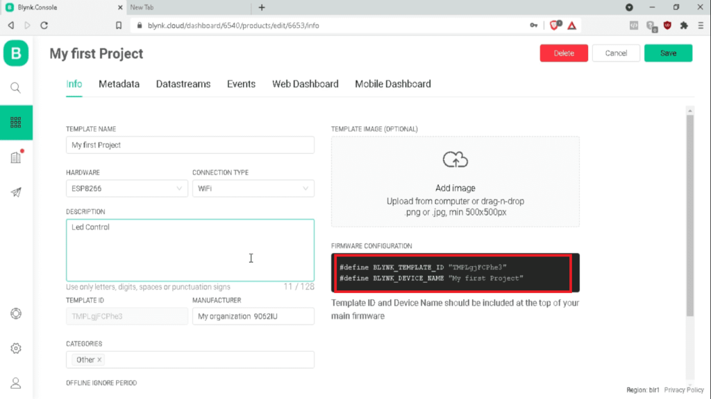
#define BLYNK_TEMPLATE_ID “TMPLgjFCPhe3”
#define BLYNK_DEVICE_NAME “My first Project”
just copy these credentials and replace.
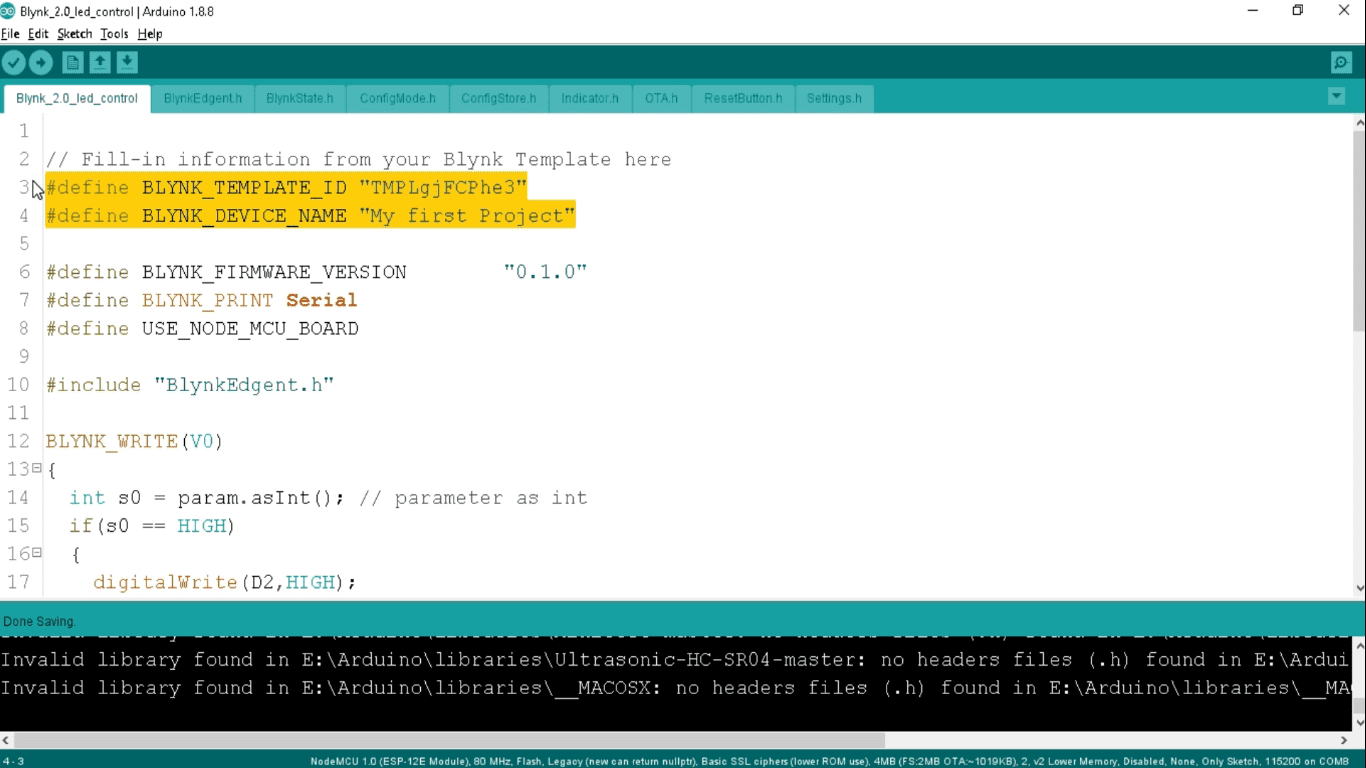
In this program, we have taken a V0 virtual pin as we have defined it to our web dashboard and in our datastream.
So here we take s0 as an integer type and store the parameter as an integer that we would receive from the virtual pin V0.
int s0 = param.asInt();
Now we compare it if we receive 1 means HIGH integer from the V0 pin when we press the switch from our web dashboard or blynk mobile app. Then we digitally high the D2 number pin by using the digital write command.
Similarly, if we receive the LOW or 0 integers, then we digitally Low the D2 pin. We connect the led at the D2 number pin of Nuttyfi.
Below is the setup function, we begin the serial at a 9600 baud rate. Define the pinMode for D2 pin as input and digitally Low the D2 pin in the starting. Here we begin the blynkagent. In the loop function, there is only one function, Blynk Edgent.run
When an event will happen in the blynk mobile app or the blynk web dashboard, it will automatically call that event.
Now, we connect the Nuttyfi/ NodeMCU board to our laptop to program it. We should have a wifi board installed into our Arduino IDE. If you don’t know how to install a wifi board, then this is a link to describe to you, how you can install it to the Arduino IDE.
i am using here ESP8266 Nuttyfi wifi development Board, Developed by Nutty Engineer Company, It is the most powerful board with the latest firmware. You can use nodemcu or other wifi development boards beside it.
So you go to the tools tab->, then Boards-> select NodeMCU 1.0 ESP12E Module board and PORT as COM8, and upload the program. And it’s done.
Now, you need to downlaod the new Blynk IoT app. go to your play store/ app store, search blynk here and you can see here blynk IoT New app. You just download it.
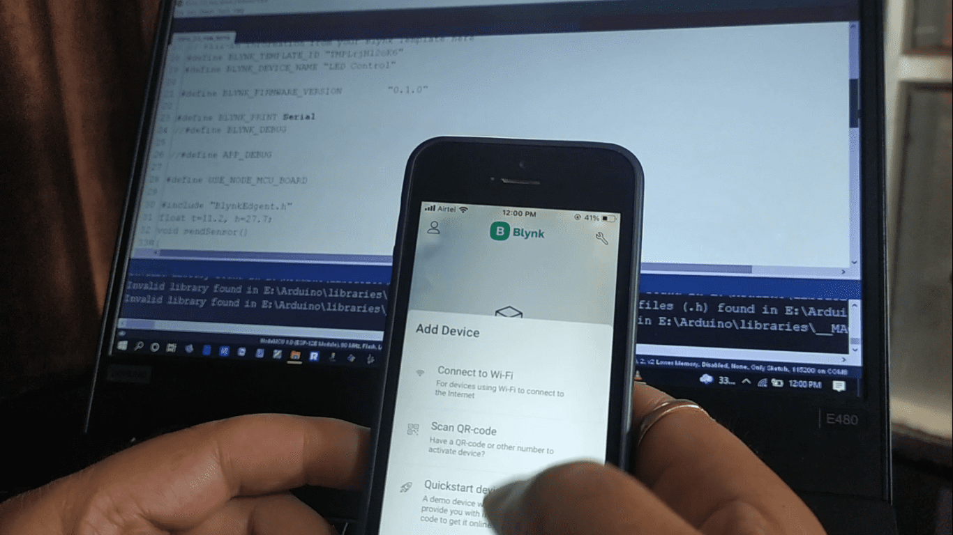
So, open and login to the app. Click on add new device and It displays the 3 options:
- Connect to wifi
- Scan QR code
- Quick start Device
Click on “Connect to wifi” option.
Now, power up your NodeMCU Nuttyfi IoT board. and Click on ready.
It starts searching for nearby blynk devices. you will get the popup that shows new blynk device detected, click on join. It’s getting the device information.
after it will ask to connect to wifi, provide the wifi credentials and done.so this is how we connect our Nuttfi NodeMCU to blynk cloud. Now back to the dashboard and you can see the template that you created in the web dashboard.
Click on the template and click on the setting symbol, the dashboard will open. Click on + sign.

Click on the button and it will automatically add to your dashboard. Now click on the button, button property will get open. Click on select datastream and select the LED (V0). Change the mode to switch and back to the dashboard. Now we can operate the led at D2 number of Nuttyfi or any ESP8266 development board.
We attach the led to the D2 no of Nuttyfi and another pin to the GND. Now let’s see the live testing of led control through the New Blynk app.
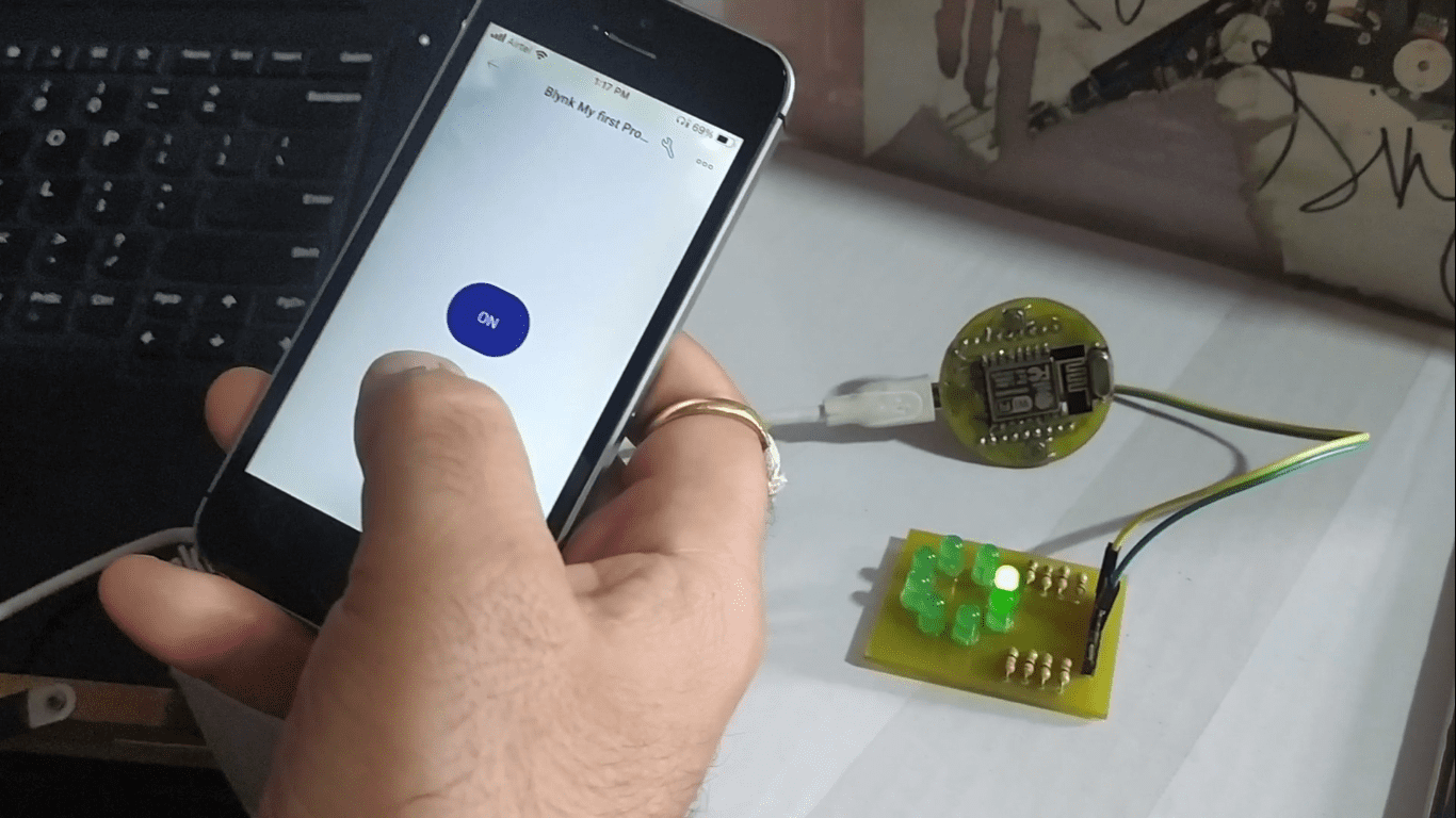
At the same time, you can control the led from the web dashboard. As you can see, we are controlling the led from the new blynk app. You can also control the same led from the web dashboard.
So this is how you configure the new web and mobile dashboard of Blynk 2.0 and control of led. You can follow this method to control any digital output device.
All the related material to this post is available to download below.
Important Links:
How to install wifi board ESPxx series to Arduino IDE. https://www.nuttyengineer.com/nuttyfi-iot-board-in-arduino-ide/
Blynk 2.0 Library: https://drive.google.com/file/d/1dzvtBPYxsUy_kWoG2KzQ3Gv39T2LETx-/view?usp=sharing
Blynk 2.0 Led control code:
https://drive.google.com/file/d/1sTyUqPYMvEEoZJUVdWLRXvIJSXNdN9oP/view?usp=sharing
Blynk cloud server: https://blynk.cloud/
Proteus Software: https://www.labcenter.com/downloads/
Arduino IDE Software: https://www.arduino.cc/en/software
Atmel AVR Studio: https://www.microchip.com/mplab/avr-support/avr-and-sam-downloads-archive
Nuttyfi Wifi Development board: https://www.nuttyengineer.com/product/nuttyfi-v2/
For any query, you can comment on the comment box below.
Like, subscribe & follow us at
YouTube channel: https://www.youtube.com/channel/UCqq3hq_jvNKX9FyZ3qj7mzA/
Twitter: https://twitter.com/itsbhupendra
LinkedIn: https://www.linkedin.com/company/schematics-micro-electronics/
Facebook: https://www.facebook.com/schematicslab
Instagram: https://www.instagram.com/itsbhupendrasingh/
Blog: https://schematicslab.blogspot.com/
Website: https://www.smedehradun.com