Hi,
If you want to make your own Arduino, then you are in the right post. We will show you how you can make your own Arduino Uno.
We have done lots of research on it & its the conclusion of it.
First of all, collect the following components so that when you start, then nothings will left behind.
- Zero Size PCB (General size pcb) – 1
- 28pin IC base – 1
- Atmega328P-PU (with Arduino bootloader) – 1
- L-Type Male Header- 1 strip
- Male Header – 1 strip
- 22pf ceramic capacitor- 2
- 104 pf capacitor- 1
- 10 k Resistor-1
And,
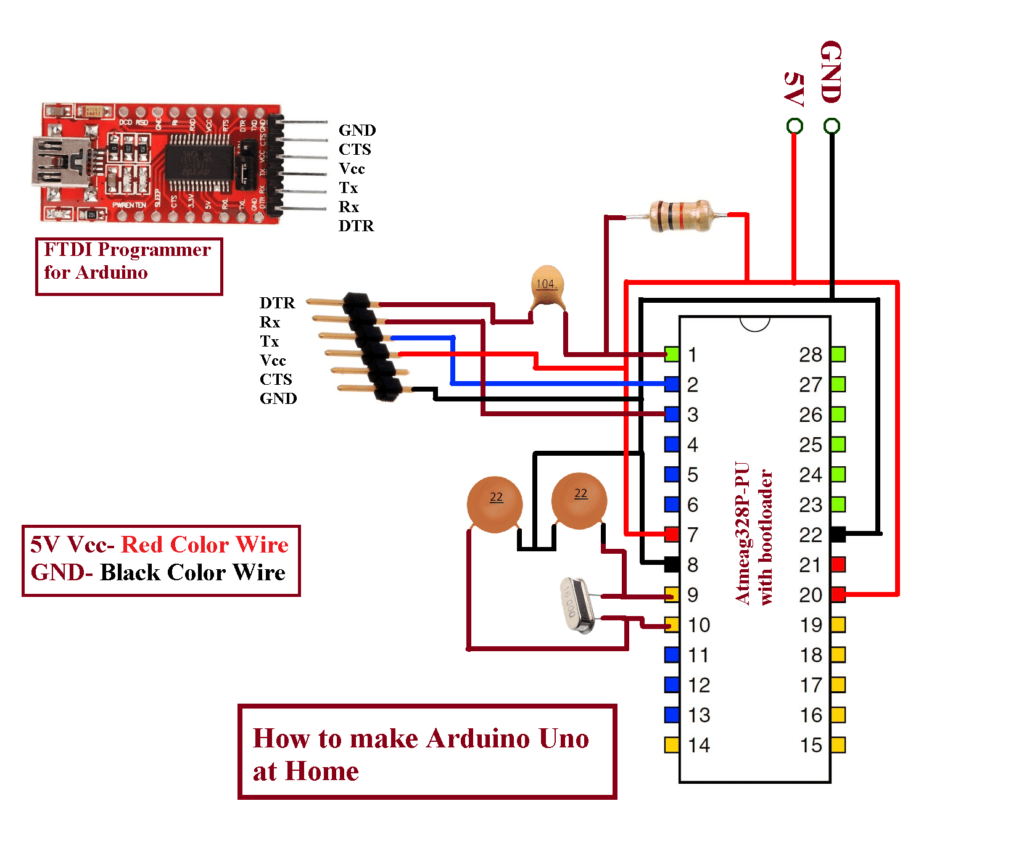
This is the circuit diagram, you have to connect all the connection as per this circuit diagram.
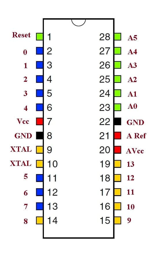
This is Atmega328P-PU pinout. Refer these pins for your Arduino Uno.
Now, place 28 pin header to the zero size pcb and solder all the pins. Now place all the components in zero size PC one by one and solder then as per the circuit diagram shown in upper image.
Once all the connections completed, then open the Arduino IDE and open the blink program or any other program to test your board. you can also watch our video for complete demo for it.
Now take FTDI programmer and connect it to the FTDI programming connectors, then connect it to the computer’s usb port.
Go to the tools-> then boards-> then select Arduino/Genuino Uno.
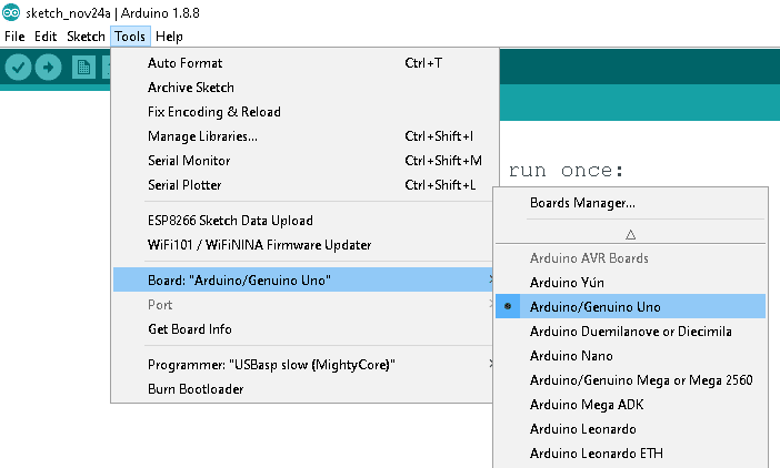
and also the PORT as COM8 and click on the upload button.

Once uploaded, your board is working.
but remember that Atmega328P-PU IC must have preloaded Arduino Uno bootloader .
So, this is how you can make your own arduino uno board at home.
You can take the help from our video tutorials, if you feels any doubt for your connections.