In this Lora Series of tutorials, we will try to make you understand, “How you can test Long range LoRa SX1278,”. Our all programs and hardware are well tested and equipped with latest firmware.
You can also contact us for your customization, definitely we will help you to design your project or product as per the industry standard.
Required components for this Project:
- LoRa SX1278
- Customized Atmega328 board/ Arduino Uno
- 12V Power adaptor
- Connecting wires if you use Arduino Uno
- 20×4 Alphanumeric LCD
LoRa Core is patented & manufactured by Semtech. The series of Lora SX1276/77/78 &79 transceivers feature the long range modem that provides ultra-long range spread spectrum communication and high interference with minimizing current consumption. So, where we talk about the application, you can use Lora in any application where you don’t want to use a public network because it creates its own network. Nowadays LoRa is widely used as an IoT Gateway for industrial application. The range of this LoRa module is near 1 km. So let’s start with a demonstration.
Below i s the circuit diagram of the LoRa Transceiver module, where we use it with arduino uno as a transmitter.
And this is a receiver board circuit where we use a 20×4 Alphanumeric LCD display with an arduino. When the transmitter board transmits the data and receiver receives and displays that data to the LCD.

Lora SX1278 Transceiver module with base is designed by the Nutty Engineer Company.
We take 2 LoRa modules, one for transmitter and another for receiver. This is the customized Atmega328 board, which is compatible with Arduino IDE software. you can take arduino uno.
On the transmitter side, Lora has 8 output pins on Lora Base, that we connected to Arduino Uno-
- GND- GND
- Vcc – 3.3v
- Nss – 10
- DIO0 – 2
- SCK – 13
- MISO – 11
- MOSI – 12
- RST – 9
and on the receiver side, Connection of LoRa to Arduino Uno-
- GND- GND
- Vcc – 3.3v
- Nss – 10
- DIO0 – 2
- SCK – 13
- MISO – 11
- MOSI – 12
- RST – 9
We also connects 20×4 LCD Alphanumeric LCD to the receiver as follows-
Once downloaded the LoRa Library, you will get the winRAR file with the name SME_LoRa_Lib. If you don’t have these software, the you can download from here
Now unzip the folder and you will get the unzip file with the same name. Copy this folder and go to the folder where you installed the arduino. Go inside it, you will get the library folder. Go inside this library folder and paste the LoRa library here.
Again, download the programming codes for LoRa transmitter and LoRa Receiver. Once downloaded, you will get the folder with the name SME_LoRa_code. when you extract it and you will get the folder with the same name. open the folder and you will get 2 folders with the name SME_LoRa_Rx and SME_LoRa_Tx.
So, open the folder with Name SME_LoRa_Tx and you will get the arduino file inside it. Open it with arduino IDE software.
So this is the program for the board that is acting as a transmitter.
LoRa Transmitter code
/*********
Modified from the examples of the Arduino LoRa library by nuttyengieer.com
for more information write to nuttyengineeronline@gmail.com or info@nuttyengineer.com
*********/
#include <SPI.h>
#include <LoRa.h>
#define ss 10
#define rst 9
#define dio0 2
int counter = 0;
void setup() {
//initialize Serial Monitor
Serial.begin(9600);
while (!Serial);
Serial.println(“LoRa Sender Tested by SME Dehradun “);
//setup LoRa transceiver module
LoRa.setPins(ss, rst, dio0);
if (!LoRa.begin(433E6)) {
Serial.println(“Starting LoRa failed!”);
while (1);
}
LoRa.setSyncWord(0xF3);
Serial.println(“LoRa Initializing OK!”);
}
void loop() {
Serial.print(“Sending packet: “);
Serial.println(counter);
//Send LoRa packet to receiver
LoRa.beginPacket();
LoRa.print(“Packet “);
LoRa.print(counter);
LoRa.endPacket();
counter++;
delay(1000);
}
First of all we define the SPI library for arduino.
#include
#include
We include the LoRa library and define the LoRa module pin as SS to 10, rst as 9 and DIO0 as 2.
#define ss 10
#define rst 9
#define dio0 2
We take counter 0 as integer type, so that we can send counter value to the LoRa receiver every second.
int counter = 0;
In the setup mode, we begin the serial port at 9600 baud rate. While we start the serial monitor, it serially displays the message “Lora Sender tested by SME Dehradun”.
void setup() {
//initialize Serial Monitor
Serial.begin(9600);
while (!Serial);
Serial.println(“LoRa Sender Tested by SME Dehradun “);
We setup the Lora module pins by defining the command lora.setpins ss, rst and DIO0.
//setup LoRa transceiver module
LoRa.setPins(ss, rst, dio0);
After it we write the command to initialize the LoRa Module at 433MHz by command Lora.begin. If it’s found the LoRa Module connected to Arduino or customized board, then it displays the message serially that “LoRa Initializing Ok” otherwise displays “Starting LoRa failed”.
if (!LoRa.begin(433E6)) {
Serial.println(“Starting LoRa failed!”);
while (1);
}
LoRa.setSyncWord(0xF3);
Serial.println(“LoRa Initializing OK!”);
}
After it we set the synchronizing word for the receiver module so that when LoRa Receiver receives the data packet after synchronizing this word.
Now inside the loop function, we serially print the counter value and then begin the LoRa Packet with LoRa.beginPacket function.
void loop() {
Serial.print(“Sending packet: “);
Serial.println(counter);
And write inside the packet space counter value. After it we end the LoRa packet with the Lora.endPacket command.
void loop() {
Serial.print(“Sending packet: “);
Serial.println(counter);
We increment the counter every second so that every time LoRa packet sends with incremented value.
counter++;
Now, Upload the program to transmitter.
Now time to open the program for LoRa Receiver. So go back to the folder and now open the SME_LoRa_Rx program.
LoRa Receiver Code
/*********
Modified from the examples of the Arduino LoRa library by nuttyengieer.com
for more information write to nuttyengineeronline@gmail.com or info@nuttyengineer.com
*********/
#include<LiquidCrystal.h>
#include <SPI.h>
#include <LoRa.h>
LiquidCrystal lcd(A0,A1, A2, A3, A4, A5);
#define ss 10
#define rst 9
#define dio0 2
int counter = 0;
void setup() {
//initialize Serial Monitor
Serial.begin(9600);
lcd.begin(20,4);
lcd.clear();
while (!Serial);
Serial.println(“LoRa Sender Tested by SME Dehradun “);
//setup LoRa transceiver module
LoRa.setPins(ss, rst, dio0);
if (!LoRa.begin(433E6)) {
Serial.println(“Starting LoRa failed!”);
lcd.setCursor(0,0);
lcd.print(“LoRa Error! “);
while (1);
}
LoRa.setSyncWord(0xF3);
Serial.println(“LoRa Initializing OK!”);
lcd.setCursor(0,0);
lcd.print(“LoRa is OK! “);
delay(3000);
}
void loop() {
// try to parse packet
int packetSize = LoRa.parsePacket();
if (packetSize) {
// received a packet
Serial.print(“Received packet ‘”);
lcd.setCursor(0,0);
lcd.print(“Received packet”);
// read packet
while (LoRa.available()) {
String LoRaData = LoRa.readString();
Serial.print(LoRaData);
lcd.setCursor(0,1);
lcd.print(LoRaData);
}
// print RSSI of packet
Serial.print(“‘ with RSSI “);
Serial.println(LoRa.packetRssi());
lcd.setCursor(0,2);
lcd.print(” with RSSI “);
lcd.setCursor(0,3);
lcd.print(LoRa.packetRssi());
lcd.print(” “);
}
}
In the receiver program we include the LCD, SPI and Lora Library. We connect the LCD pins to A0, A1, A2, A3, A4 and A5. Now we define the LoRa pins at ss 10, rst 9 and DIO0 at 2 no pin.
#include<LiquidCrystal.h>
#include <SPI.h>
#include <LoRa.h>
LiquidCrystal lcd(A0,A1, A2, A3, A4, A5);
#define ss 10
#define rst 9
#define dio0 2
In the Setup function, we begin the serial at 9600 baud rate. Begin the 20×4 lcd. Clear the lcd and write the LoRa.setPins command. We begin the Lora module at 433Mhz and if it is not initialized, then we write the serial command to print as Starting LoRa failed and also print “LoRa Error!” in the LCD.
And if it initializes correctly, then it synchronizes the set word as 0xF3 as similar to the set in the transmitter and serially writes the message “Lora Initializing OK” and at the same time it prints “LoRa is OK” in LCD.
if (!LoRa.begin(433E6)) {
Serial.println(“Starting LoRa failed!”);
lcd.setCursor(0,0);
lcd.print(“LoRa Error! “);
while (1);
}
LoRa.setSyncWord(0xF3);
Serial.println(“LoRa Initializing OK!”);
lcd.setCursor(0,0);
lcd.print(“LoRa is OK! “);
delay(3000);
}
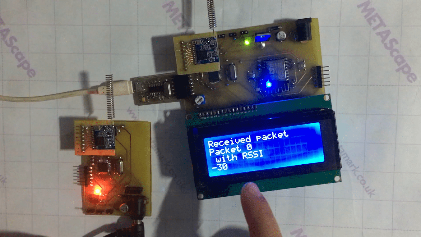
You can see, the LCD is displaying the Packet received from the transmitter with RSSI strength.
As we are using the customized Boards that is compatible with Arduino IDE as well as ATmel AVR Studio for for This purpose. Then you see this testing in customized boards.
That’s all done.
Important Links:
Circuit Diagrams for Lora Transceiver:
Transmitter: https://drive.google.com/file/d/1YXgwvEC2pW_ERi_3hWPvZXloc0Yw3smL/view?usp=sharing
Receiver: https://drive.google.com/file/d/16k4I-L01Zacm6D79M-_ID_OyJJd5nK1k/view?usp=sharing
How to install wifi board ESPxx series to Arduino IDE: https://www.nuttyengineer.com/nuttyfi-iot-board-in-arduino-ide/
LoRa Library: https://drive.google.com/file/d/1XHWMfdtfJPjTFjGz6wxV73Jn2MFccumZ/view?usp=sharing
SPI Lib for Arduino: https://github.com/arduino/ArduinoCore-avr
Lora Programming codes: https://drive.google.com/file/d/1tZg6FWgFxbVYqWfrjBIzVYfeFfxRGPcy/view?usp=sharing
How to install ftdi/ ch340 driver: https://www.nuttyengineer.com/how-to-install-ftdi-usb-to-uart-bridge-drivers/
Blynk cloud server: https://blynk.cloud/
Proteus Software: https://www.labcenter.com/downloads/
Arduino IDE Software: https://www.arduino.cc/en/software
Atmel AVR Studio: https://www.microchip.com/mplab/avr-support/avr-and-sam-downloads-archive
Nuttyfi Wifi Development board: https://www.nuttyengineer.com/product/nuttyfi-v2/
Link to download winzip: https://www.winzip.com/en/download/winzip/
Link to download WinRAR: https://www.win-rar.com/download.html?&L=0
Contact link for Nutty Engineer Company: https://www.nuttyengineer.com/contact-us/
For any query, you can comment on comment box below.
Like, subscribe & follow us at
YouTube channel: https://www.youtube.com/channel/UCqq3hq_jvNKX9FyZ3qj7mzA/
Twitter: https://twitter.com/itsbhupendra
LinkedIn: https://www.linkedin.com/company/schematics-micro-electronics/
Facebook: https://www.facebook.com/schematicslab
Instagram: https://www.instagram.com/itsbhupendrasingh/
Blog: https://schematicslab.blogspot.com/
Website: https://www.smedehradun.com
I studying BTech final year in my minor project is same project. We used the Arduino UNO board, SX1278 LoRa module and LCD. But we cant reach the distance 1km or else we cant reach the 500m also we got the 350m and we used 3dbi antennas. Can u please help me to complete the project.
The range depends on the data packet, the gain of the antenna you are using, the geographical area, and the placement height. To improve the range, you can use an external antenna and position it at a height that maximizes coverage.
I am sending single character, used 9dbi antenna and antenna is placed on the 3rd floor of my building.